Global web icon
watelectronics.com
https://www.watelectronics.com/what-is-amplitude-m…
Amplitude Modulation - Types, Derivatives, Block Diagram and Applications
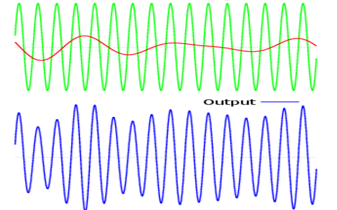
What is Amplitude Modulation? In general, Amplitude Modulation is termed as modulating a continuous transmitting wave that has no intervals and holds the information.
Global web icon
cbnu.ac.kr
http://ael.cbnu.ac.kr/lectures/undergraduate/micro…
Principles of Electronic Communication Systems - CBNU
Explain the relationship of the basic equation for an Am signal to production of amplitude modulation, mixing and frequency conversion by a diode or other nonlinear frequency component or circuit.
Global web icon
researchgate.net
https://www.researchgate.net/figure/Block-diagram-…
Block diagram of Amplitude Modulation and Demodulation.
Block diagram of Amplitude Modulation and Demodulation. The use of voltage differencing current conveyor as an active device to design a current-mode oscillator along with a universal...
Global web icon
nrcmec.org
https://www.nrcmec.org/pdf/Manuals/ECE/AC%20LAB%20…
EXPERIMENT NO-1 AMPLITUDE MODULATION &DEMODULATION
PROCEDURE:- Measure the frequency & amplitude (p-p) of the fixed carrier signal present on the kit. Connect the circuit as per the given circuit diagram. Apply fixed frequency carrier signal to carrier input terminals. Apply modulating signal from function generator of 1VP-P of 500Hz.
Global web icon
circuitdiagram.co
https://www.circuitdiagram.co/amplitude-modulation…
Amplitude Modulation And Demodulation Circuit Diagram
This circuit diagram consists of an input, an amplifier, and a demodulator. The input to the circuit is the modulated signal, which is then amplified and sent to the demodulator.
Global web icon
njit.edu
https://ecelabs.njit.edu/ece489v2/Lab1.php
ECE 489 Lab 1: Amplitude Modulator and Demodulator
This code will open the Simulink Model of DSB-AM modulator and demodulator techniques based on Envelope Detector by Squaring and Hilbert Transform. Run your simulation to observe the waveform in time domain
Global web icon
eeeguide.com
https://www.eeeguide.com/modulation-and-demodulati…
Modulation and Demodulation Articles - EEEGUIDE.COM
Block Diagram of AM Transmitter: Block Diagram of AM Transmitter is shown in Fig. 22.25. Sound waves produced by speech or music strike the diaphragm of a microphone that converts them into a tiny varying current.
Global web icon
cuhk.edu.hk
https://www.ee.cuhk.edu.hk/~wkma/eleg2310/handouts…
Handout 4: Amplitude Modulation - Chinese University of Hong Kong
We consider an alternative AM demodulator approach whose block diagram is illustrated in Fig-ure 5. The idea is intuitively similar to the simple envelope detector in Figure 4.
Global web icon
kfupm.edu.sa
https://faculty.kfupm.edu.sa/ee/muqaibel/Courses/E…
Amplitude Modulation - KFUPM
The modulator/demodulator system shown above clearly is able to modulate and demodulate two different signals without any interference. However, if the generation of the carrier at the demodulator had even small phase or frequency errors, the demodulated signals will interfere at the outputs.
Global web icon
svcetedu.org
https://svcetedu.org/Uploads/ECE/acdclab1.pdf
AMPLITUDE MODULATION AND DEMODULATION
The Pulse Amplitude Demodulator consists of Active Low Pass Butterworth filter. It filters out the sampling frequency and their harmonics from the modulated signal and recovers the base band by integrated action.